← SHEET 02 · ASSEMBLIES HW-002
Folding Parallelogram Staircase
| PART NO | HW-002 |
|---|---|
| MATL / SYSTEM | STEEL 4-BAR LINKAGE |
| TOOLS | FreeCAD · Python macro |
This one started as a problem in my own bedroom. I wanted to split the room into levels — the original floor, a sunken office one level down, and a sleeping platform above — but a fixed staircase would have eaten the floor area that made the idea worth doing. The answer was a stair that exists only when you need it: a folding parallelogram linkage whose six treads stay perfectly level on the way down and fold flush into the floor when stowed. It went from a hand drawing to a parametric FreeCAD model to a real welded-steel mechanism, built together with my father, and it now carries me down to the office every day.
OVERVIEW & MOTIVATION
The room is being reorganized into three levels: the original floor (level 1),
a −1 level below it that holds my working office, and a level 2 above for the bed
and rest area (its connecting platform between levels 1 and 2 is still under
construction). This stair is the link from the original floor down to the office.
The requirement that drove the whole design: near-zero footprint when stowed —
the treads tile shut into the 1720 × 760 mm floor opening and the hatch is
walkable — but a full, comfortable staircase geometry when deployed. The design
sequence was deliberate: first a manual drawing to get the linkage concept right,
then the parametric FreeCAD macro (fold_stair_full.FCMacro) to lock the
kinematics and dimensions, then construction to those dimensions.
MECHANISM & KINEMATICS
The stair is a parallelogram four-bar: fixed pivot A, ground pivot B offset by the 160 mm ground link, two parallel rails of equal length running from A and B, and a coupler (tread bracket) connecting corresponding points on both rails. Because the coupler length is fixed at the same 160 mm as the ground link, and both rails rotate together as parallel members, every coupler stays parallel to A→B through the whole swing — so each tread translates along a circular arc without rotating relative to the floor. That’s what keeps six treads level at any fold percentage, from vertical (closed) to the 46° deployed stair angle.
Rail length is derived from rise as the master dimension: RAIL_LEN = RISE / sin(DEPLOY_ANGLE) = 900 / sin(46°) ≈ 1251 mm. In the closed pose, rails rotate to vertical (90°) and treads nest into their flush position tiling the floor opening.
| PARAMETER | VALUE | UNIT |
|---|---|---|
| RISE (floor-to-floor, master dimension) | 900 | mm |
| OPENING_LEN (hatch, along run) | 1720 | mm |
| OPENING_WID (hatch, across) | 760 | mm |
| GROUND_LINK (A→B) | 160 | mm |
| DEPLOY_ANGLE | 46 | deg |
| RAIL_LEN (solved) | ≈1251 | mm |
| N_TREADS | 6 | count |
| TREAD_PITCH_CLOSED (OPENING_LEN / N_TREADS) | ≈287 | mm |
| TREAD_DEPTH (pitch × 0.98, gap allowance) | ≈281 | mm |
| TREAD_WIDTH (OPENING_WID × 0.97) | ≈737 | mm |
| TREAD_THICK | 30 | mm |
| RAIL_W × RAIL_H (cross-section) | 40 × 40 | mm |
| FLOOR_THICK | 40 | mm |
PARAMETRIC MODEL
Everything downstream is driven off the parameter block at the top of the macro.
RISE is the master dimension: change it and RAIL_LEN re-solves through the
deploy-angle relation, tread pitch re-derives from OPENING_LEN / N_TREADS, and
every rail, coupler, tread, and latch placement recomputes. A single pose(fold01)
function interpolates the whole assembly between deployed (0.0) and closed (1.0):
rails rotate about A/B, tread brackets ride the linkage exactly, and treads
themselves blend between their linkage-driven deployed midpoint and a flush,
floor-level closed target so the hatch tiles cleanly when shut. A Qt dock widget
(PySide6/PySide2/PySide shim for cross-version FreeCAD) exposes a 0–100
slider plus a “Play open/close” button that steps the pose over a 4-second
animation, so the fold can be scrubbed or played live inside FreeCAD.
AS-BUILT
The mechanism has been fabricated in steel and assembled in the room, built together with my father to the modeled dimensions — the 900 mm rise, 160 mm links, 46° deploy angle, and six treads all carried straight from the FreeCAD parameter block to the physical build. Two manual latches hold the closed hatch level and walkable. Remaining work on the room itself: the level-2 sleeping platform and its connection between levels 1 and 2 are still under construction. Planned refinements to the stair: rebuild the CAD as a proper jointed FreeCAD assembly (real revolute joints at A, B, and the coupler pins rather than placement math), and size a self-locking 12 V linear actuator for motorized deployment against the ≈1251 mm rail geometry and 900 mm rise.
BUILD PHOTOS
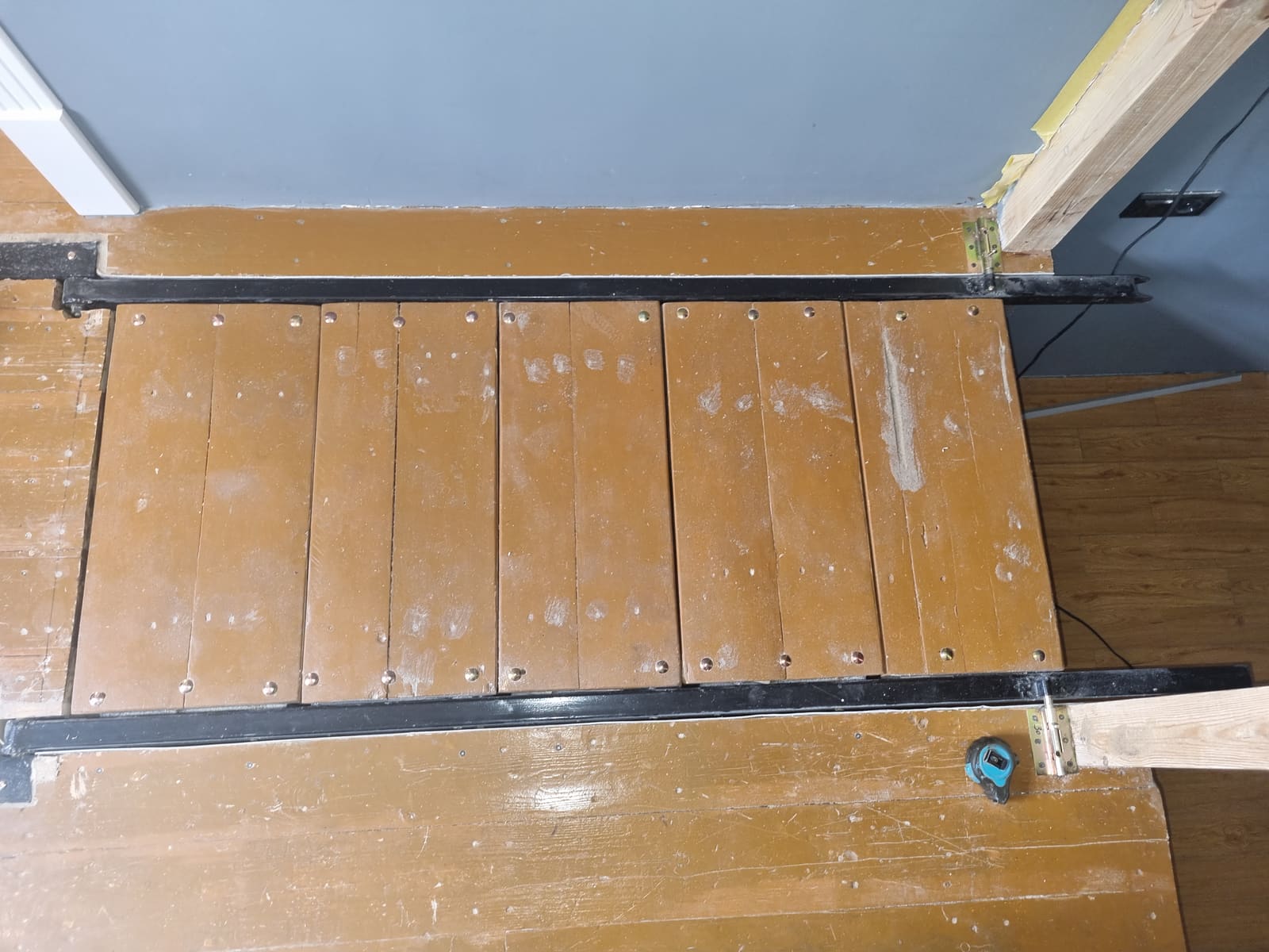 CLOSED — hatch shut, treads tiling the 1720 × 760 mm opening flush with the floor.
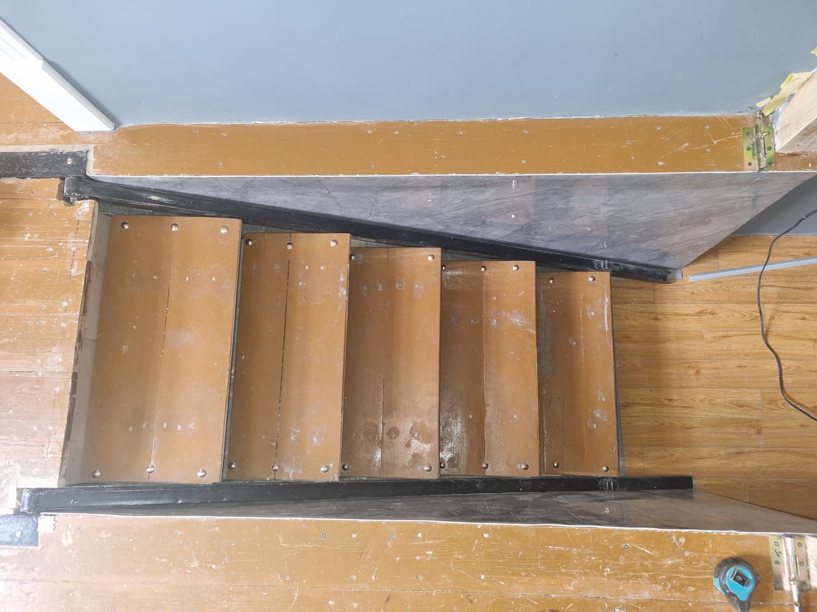 DEPLOYED, FROM ABOVE — treads stay level as the parallelogram swings them down.
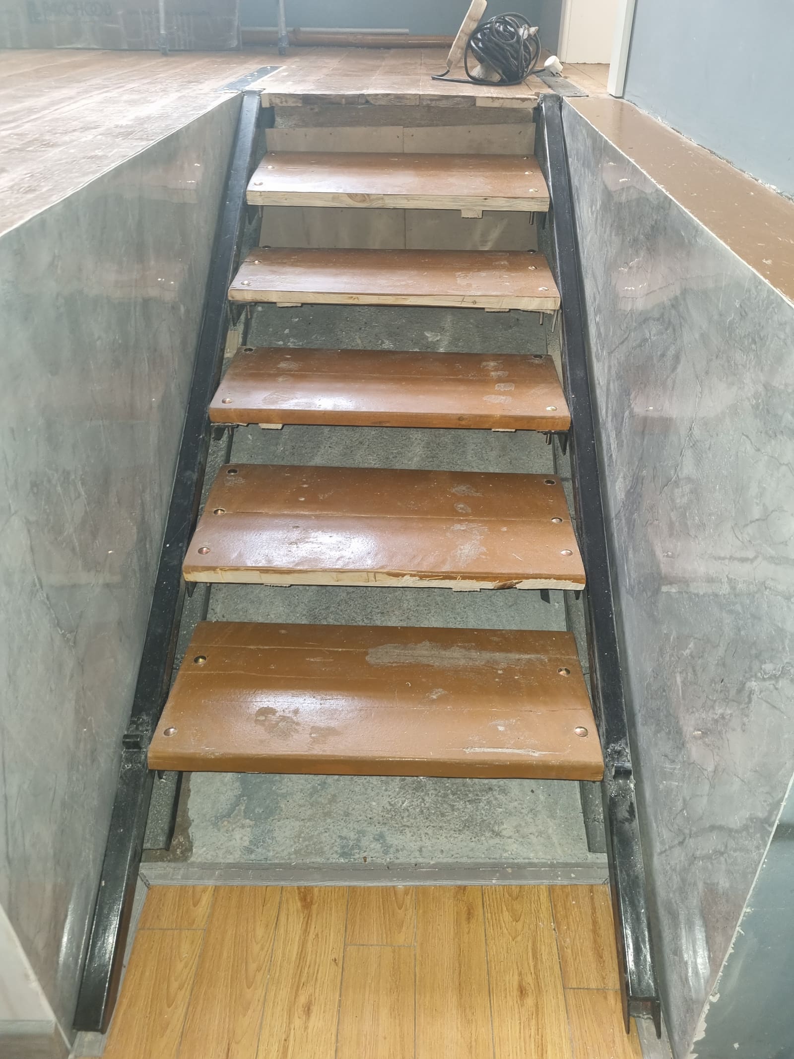 DEPLOYED, FROM THE −1 OFFICE — welded steel rails, timber treads, 46° stair angle.
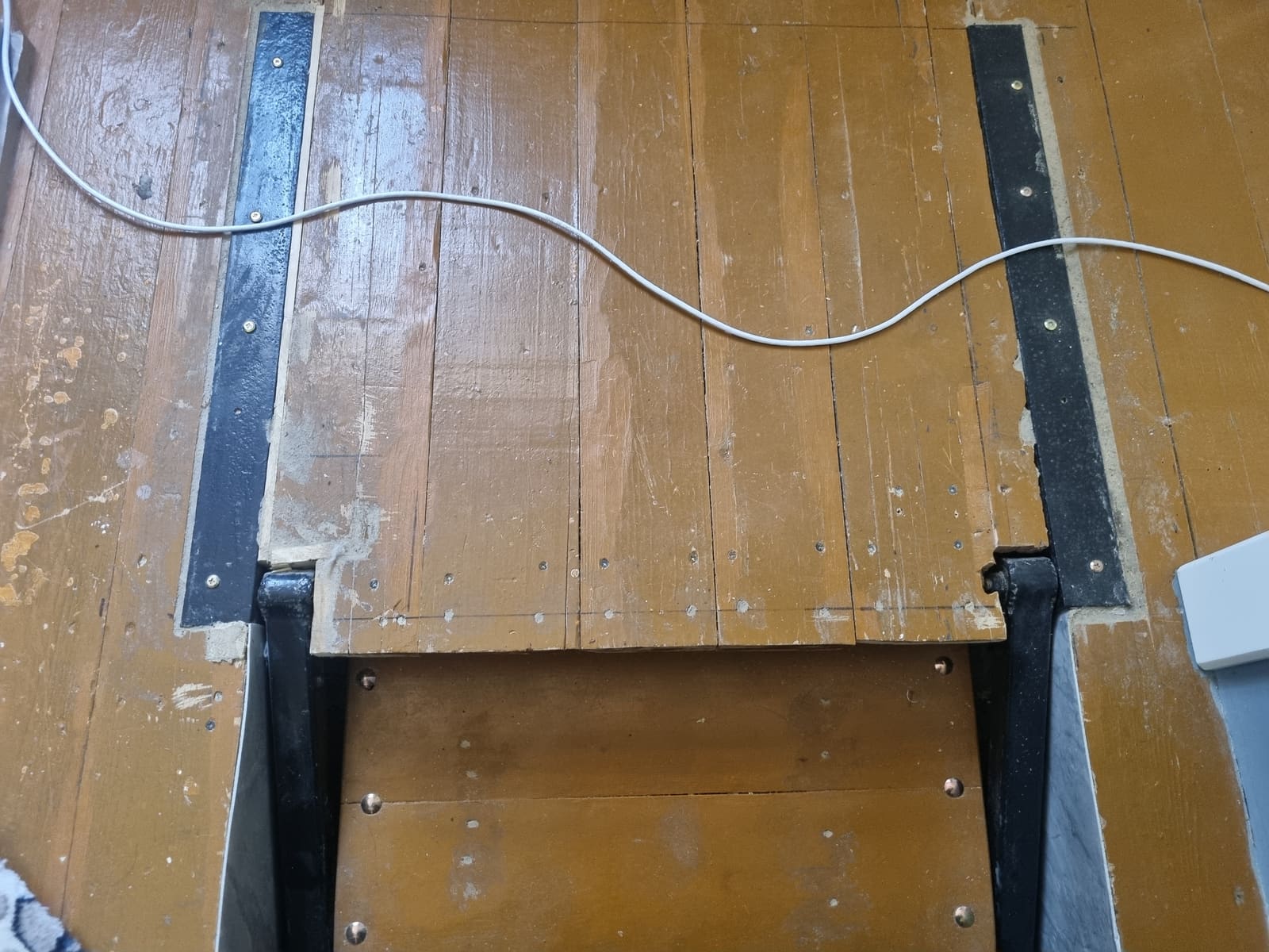 RAIL DETAIL — steel frame recessed into the floor line at the pivot end of the opening.
USE CASES & APPLICATIONS
Space-saving retractable stairs for lofts, tiny homes, and attic access, where a folding hatch stair needs to disappear flush into the floor when not in use. Accessible mezzanine access in tight footprints, and aircraft or RV integrated steps that stow behind a hatch. More generally, the parallelogram four-bar that keeps the treads level is the same principle behind level-luffing cranes, parallel drafting machines, and any mechanism that must keep a working platform level while its support swings through an arc.
FILES & REPRODUCTION
Source: fold_stair_full.FCMacro. To run it, open FreeCAD, open the Macro editor,
paste the script, and execute — it creates a new document, builds the floor slab
with its cut hatch, both rail pairs, tread brackets, six treads, and two latches,
then opens the “Fold stair control” dock panel with the slider and Play button. The
site’s 3D viewport embeds a GLB export of the deployed pose for interactive
viewing.